Nullcon Berlin CTF 2024
HackMe Hardware Challenges - Nullcon Berlin CTF 2024
The 6 challenges below use the same PCB.
Update March 16, 2024: I forgot another fix we had to do for the first challenge + added solution to the last HackMe challenges.
HackMe Fix the Board (5 solves)
The PCB we are given does not work as such: the screen does not light up and the device does not boot correctly. We’ve got to repair it.
Fix 1
As the screen does not light up, there has to be a power issue. From VCC, we notice there is a Diode, U14, which is in the wrong direction, thus blocking current.
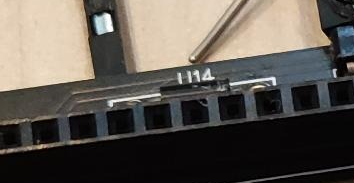 Diode U14 is in the wrong direction
We let the current pass by simply bypassing the diode. I solder a wire from VCC to the other end of U14.
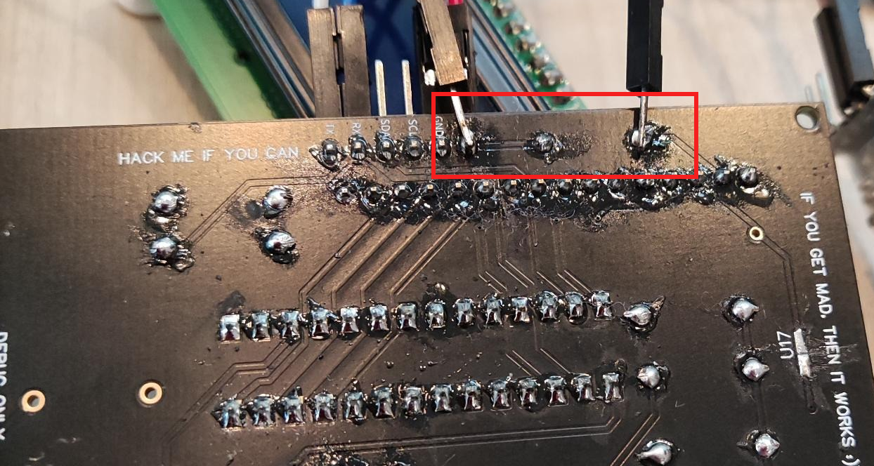 Simply bypassing the diode with a wire
Fix 2
We notice that the track by U17 has been (intentionally) cut by the organizers ;) We just need to solder that again.
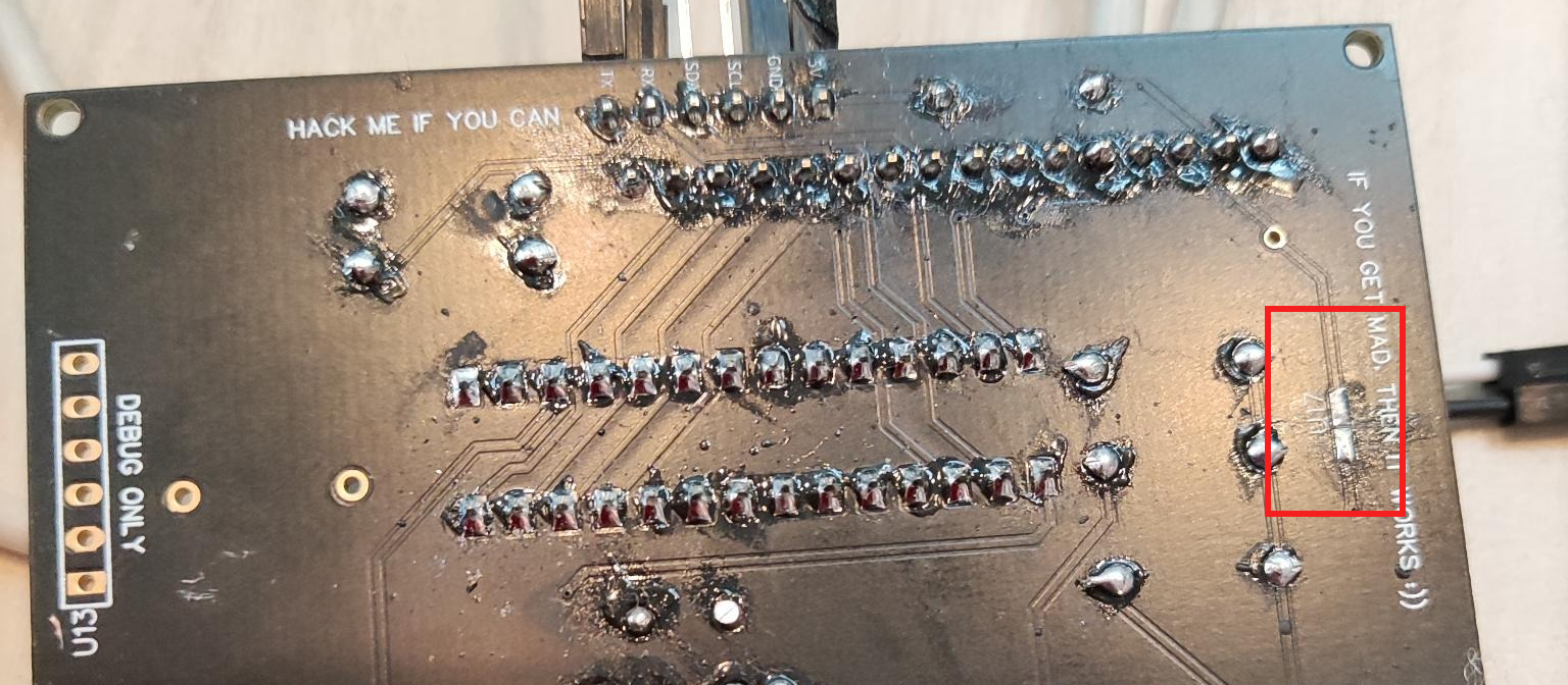 The track is cut. We’ve got to fix that
Fix 3
The same also occurs on a track below the screen: intentionally cut, you just need to add solder. It shows on the photo below (Fix 4 - U15 if I read correctly), just left of the resistor.
Fix 4
A resistor was marked ? and needed to be removed. I didn’t have any scissors, so I did it the caveman-way: heated up one end of the soldering while pushing with a screwdriver from beneath to get the resistor out of its socket. Fortunately, an organizer gave me a hand, because my procedure wasn’t very safe…
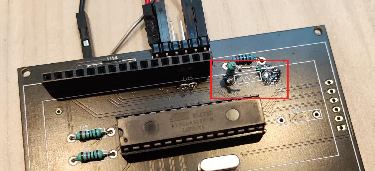 Disconnected the resistor
Flag
Once all those fixes are done, you can power the device using a USB-TTL, and the screen lights up :) You might also have to turn a potentiometer to see the message which gives you the first flag LCD.
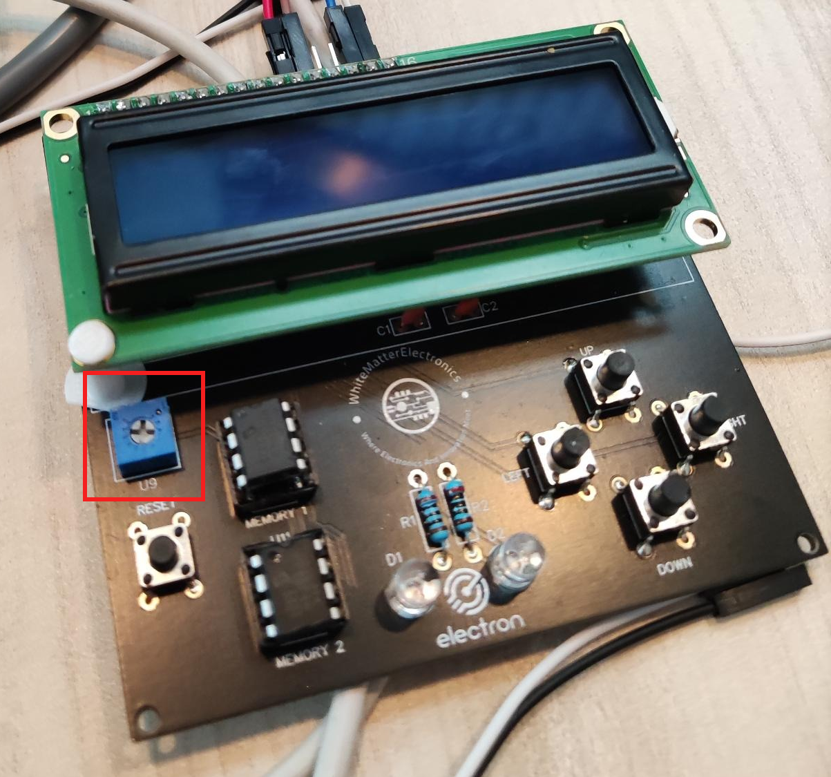 Use the potentionmeter to adjust screen’s contrast
The screen shows several menus, each one consisting in the next challenges to unlock.
I enjoyed this challenge because I’m a n00b at hardware and it wasn’t too difficult. For an even more enjoyable experience, I would recommend having a fixed flag format (
LCDdoes not look like a flag…) + adding more logic to why we absolutely need to fix the broken tracks and remove the resistor.
HackMe Dump the memory (3 solves)
The next 2 challenges consist in dumping the 2 EEPROMs labeled “MEMORY 1” and “MEMORY 2”.
I follow the beginning of this tutorial for the wiring, but actually it’s quite simple: VCC goes to 5V, SDA goes to A4 and SCL goes to A5. The rest goes to the ground.
The, I use the code of this blog post to read an I2C memory. I just modify the output to break lines every x characters.
Compile the Arduino sketch using “ATmega328P Old bootloader”. This information was given by the organizers (when I failed to upload my sketch with the standard bootloader).
| |
I am actually quite lucky: I guessed the I2C memory’s address: 0x50. I should have used an I2C scanner.
The memory dump provides lots of garbage, and in the middle:
| |
The flag is LOW ON MEMORY.
I had forgotten to take my Hydrabus to Nullcon CTF. Lesson learned: never go to a CTF without your Hydrabus! However, I really enjoyed dumping the EEPROM using a basic Arduino Nano.
HackMe Dump memory 2 (2 solves)
To dump the second memory, I use exactly the same strategy. This time, the dump contains the following:
| |
The flag is not pfl uldgvudv, nor pfluldgvudv, nor p f l u l d g v u d v. This looks like a simple alphabet translation. I use an online decoder which easily bruteforces the shift.

Do not forget the space after the 3rd letter. The flag is you dumpedme.
IMHO, this stage is slightly redundant. The encrypted message is too short to do an educated guess on the encryption algorithm, and I was a bit lucky. Also, I didn’t notice the space after the 3rd character at first and couldn’t understand why flag
youdumpedme(no space) didn’t work…
HackMe UART Password (1 solve)
I connect to the serial port of the board using picocom. It tells us to login as root, but asks for a password.
If we search in our EEPROM dumps again, we find pass:xvxz in the first dump:
| |
I get hinted by the organizers that the password is very simple, so probably only 4 characters, and probably again a translation. This time, the online decoder does not give me the password, and I get hinted again that I should use more ASCII characters.
I run the following Python snippet to view all possible translations of xvxz
| |
One of the output catches my eye: 2024
| |
Use root and 2024 to login successfully. You get the following message:
| |
Actually the flag is not HACKER CURIOSITY (error?) but 2024.
Hiding the UART password is a good idea, but the algorithm is weak and the solution requires too much guessing IMHO. I think the challenge could be improved by hiding a longer message like “UART password: 2024” and encoding that in Base64.
HackMe Write 129 at address 800 (1 solve)
The UART prompt provides a menu with several options:
| |
If we press (1) it dumps the output of EEPROM 1, and (2) dumps the output of EEPROM 2.
On the device itself (and in the title of the challenge), it tells us to write value 128 at address 129 to get a flag.
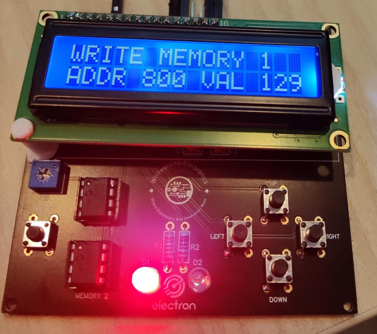
So, we select menu (3) and do that:
| |
Then, on the board, we select the menu “TELL ME 129”, and run “check for flag”. It sees we have written the address and provides us with the flag. (I forgot which one it was).
I liked this part, it was easy but it was fun to use both the serial menu and the boards menu.
HackMe Hidden in plain sight (1 solve)
Finally, the last challenge tells us there is a final message “hidden in plain sight”.
The issue is that a message can be hidden in so many places… I search on the EEPROM dumps and ask organizers for confirmation I’m on the correct path. I am. They tell me “it is really hidden in plain sight” but that I have to look well.
It will be easier if the EEPROM is dumped in an aligned format, and that’s what menu 1 and 2 do very well.
| |
It is at the end of the EEPROM. See image below. The flag is ORANGE, who is a sponsor of the board.
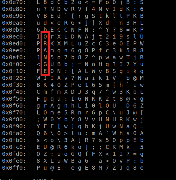
This step does not really involve computer science skills, it’s more like cross-words. I wouldn’t have completed it without hints, as the initial description does not suggest any particular direction.